| Afghan Energy, Chemical & Mining Industries resource for Renewable Energies, Irrigation & Sustainable Industries. |
Nitric Acid ProductionPrefaceIn 1995, the European Fertilizer Manufacturers Association (EFMA) prepared eight Booklets on Best Available Techniques (BAT) in response to the proposed EU Directive on integrated pollution prevention and control (IPPC Directive). These booklets were reviewed and updated in 1999 by EFMA experts drawn from member companies. They cover the production processes of the following products:
The Booklets reflect industry perceptions of what techniques are generally considered to be feasible and present achievable emission levels associated with the manufacturing of the products listed above. The Booklets do not aim to create an exhaustive list of BAT but they highlight those most widely used and accepted. They have been prepared in order to share knowledge about BAT between the fertilizer manufacturers, as well as with the regulatory authorities. The Booklets use the same definition of BAT as that given in the IPPC Directive 96/61 EC of 1996. BAT covers both the technology used and the management practices necessary to operate a plant efficiently and safely. The EFMA Booklets focus primarily on the technological processes, since good management is considered to be independent of the process route. The industry recognises, however, that good operational practices are vital for effective environmental management and that the principles of Responsible Care should be adhered to by all companies in the fertilizer business. The Booklets give two sets of BAT emission levels:--
The emission levels refer to emissions during normal operations of typical sized plants. Other levels may be more appropriate for smaller or larger units and higher emissions may occur in start-up and shut-down operations and in emergencies. Only the more significant types of emissions are covered and the emission levels given in the Booklets do not include fugitive emissions and emissions due to rainwater. Furthermore, the Booklets do not cover noise, heat emissions and visual impacts. The emission levels are given both in concentration values (ppm, mg.m -3 or mg.l -1 ) and in load values (emission per tonne of product). It should be noted that there is not necessarily a direct link between the concentration values and the load values. EFMA recommends that the given emission levels should be used as reference levels for the establishment of regulatory authorisations. Deviations should be allowed as governed by:- - Local environmental requirements, given that
the global and inter-regional environments are not adversely affected If authorisation is given to exceed these BAT emission levels, the reasons for the deviation should be documented locally. Existing plants should be given ample time to comply with BAT emission levels and care should be taken to reflect the technological differences between new and existing plants when issuing regulatory authorisations, as discussed in these BAT Booklets. A wide variety of methods exist for monitoring emissions. The Booklets provide examples of methods currently available. The emission levels given in the Booklets are subject to some variance, depending on the method chosen and the precision of the analysis. It is important when issuing regulatory authorisations, to identify the monitoring method(s) to be applied. Differences in national practices may give rise to differing results as the methods are not internationally standardised. The given emission levels should not, therefore, be considered as absolute but as references which are independent of the methods used. EFMA would also advocate a further development for the authorisation of fertilizer plants. The plants can be complex, with the integration of several production processes and they can be located close to other industries. Thus there should be a shift away from authorisation governed by concentration values of single point emission sources. It would be better to define maximum allowable load values from an entire operation, eg from a total site area. However, this implies that emissions from single units should be allowed to exceed the values in the BAT Booklets, provided that the total load from the whole complex is comparable with that which can be deduced from the BAT Booklets. This approach will enable plant management to find the most cost-effective environmental solutions and would be to the benefit of our common environment. Finally, it should be emphasised that each individual member company of EFMA is responsible for deciding how to apply the guiding principles of the Booklets. Brussels, April 2000 1. Introduction This Booklet is concerned with the environmental issues resulting from the production of nitric acid. It deals with gaseous, liquid and solid waste discharges to air, water and land and the actions to be taken to minimise such discharges. All plants for the production of nitric acid are currently based on the same basic chemical operations:- - Oxidation of ammonia with air to give nitric
oxide The efficiency of the first step is favoured by low pressure whereas that of the second is favoured by high pressure. These considerations, combined with economic reasons give rise to two types of nitric acid plant, single pressure plants and dual pressure plants. In the single pressure plant, the oxidation and absorption steps take place at ess entially the same pressure. In dual pressure plants absorption takes place at a higher pressure than the oxidation stage. The oxidation and absorption steps can be classified as:- - Low pressure (pressure below 1.7bar) Except for some very old plants, single pressure plants operate at medium or high pressure and dual pressure plants operate at medium pressure for the oxidation stage and high pressure for the absorption. The main unit operations involved in the nitric acid process are the same for all types of plant and in sequential order these are:- - Air filtration The typical plants described in this Booklet will be limited to the single pressure plant and to the dual pressure, medium pressure/high pressure plant, as the absorption is always based on medium or high pressures. These are the processes most used in the European industry. The fertilizer industry uses weak nitric acid in the range of 50 to 65% strength and thus the high concentration (above 70% weight) nitric acid production process is not included. A typical plant of 1,000t.d -1 capacity has been selected for further description but all data are calculated for one tonne of 100% nitric acid because plant size has only a marginal effect on input and output-specific data, apart from energy. The most common energy scheme has been adopted. That is: make up power for the compressor set power supplied by a condensing steam turbine, energy recovery from tail gas in a gas turbine and pumps driven by electric motors. Raw materials (ammonia and demineralised water) and cooling water facilities are required in addition to the nitric acid process unit itself, as well as an auxiliary boiler which is used by some units for start-up. The production of ammonia is covered by EFMA BAT Booklet No. 1. 2. Description of Production Process 2.1 �Processes used by the European Fertilizer Industry At the end of 1992 a tentative survey of the type of plants still in operation within the European Community gave the following results. Plants are classified by oxidation pressure and absorption pressures.
The typical capacity of the newest plants is 1000.d-1 These plant numbers are probably optimistic as the European industry is engaged in considerable rationalisation. The various processes used in Europe are discussed below and further details can be found in Reference [1]. � Ammonia is reacted with air on platinum/rhodium alloy catalysts in the oxidation section of nitric acid plants. Nitric oxide and water are formed in this process according to the main equation:- � � � � 4NH3 + 5O2 � -----> 4NO + 6H2O � � � � � � � � � � � � � � � � � � � � � � � � � � � � � � � � � � � � (1) Simultaneously nitrous oxide, nitrogen and water are formed as well, in accordance with the following equations:- � � � � 4NH3 + 3O2 -----> 2N2 + 6H2O � � � � � � � � � � � � � � � � � � � � � � � � � � � � � � � � � � � � � � (2) � � � � 4NH3 + 4O2 � -----> 2N2O + 6H2O � � � � � � � � � � � � � � � � � � � � � � � � � � � � � � � � � � (3) The yield of nitric oxide depends on pressure and temperature as indicated in the table.
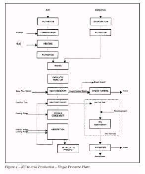
The catalyst typically consists of several woven or knitted gauzes formed from wire containing about 90% platinum alloyed with rhodium for greater strength and sometimes containing palladium. Air pollution and contamination from the ammonia can poison the catalyst. This effect, as well as poor ammonia-air mixing and poor gas distribution across the catalyst, may reduce the yield by 10%. Some of the platinum and rhodium vaporises during the reaction process and in most cases a platinum recovery system is installed below the catalyst. In this system a palladium alloy, known as a "getter" or catchment, allows a 60 to 80% recovery of the total catalyst losses. The enthalpy of the hot reaction gases is used to produce steam and/or to preheat the waste gas (tail gas). The heated waste gas is discharged to the atmosphere through a gas turbine for energy recovery. The combustion gas after this heat transfer for energy recovery, has a temperature of 100 to 200 �C, depending on the process and it is then further cooled with water. The water produced in reactions (1) to (3) is then condensed in a cooler-condenser and transferred to the absorption column. Nitric oxide is oxidised to nitrogen dioxide as the combustion gases are cooled, according to the equation:- � � � � 2NO + O2 � <---> � 2NO2 � � � � � � � � � � � � � � � � � � � � � (4) For this purpose,secondary air is added to the gas mixture obtained from the ammonia oxidation to increase the oxygen content to such a level that the waste gas leaving the plant has a normal oxygen content of between 2 and 4% by volume. The absorber is operated with a counter-current flow of water. The absorption of the nitrogen dioxide and its reaction to nitric acid and nitric oxide take place simultaneously in the gaseous and liquid phases according to equations (4) and (5). These reactions depend on pressure and temperature to a large extent and are favoured by higher pressure and lower temperature. 3NO2 + H2O � <---> 2HNO3 + NO � � � � � � � � � � � � � (5) <Reaction (5) is exothermic and continuous cooling is therefore required within the absorber. As the conversion of NO to NO2 is favoured by low temperature, this reaction will take place significantly until the gases leave the absorption column. The nitric acid produced in the absorber contains dissolved nitrogen oxides and is then bleached by the secondary air. 2.3 Medium Pressure, Single Pressure Plants A typical plant is represented in the block diagram in Figure 1 and includes:- Ammonia evaporation section Ammonia filtration section Air filtration section Air compression section Mixing section Catalytic reactor section Heat recovery sections Cooling section
Absorption section Demineralised water or steam condensate is added at the top of the tower as make-up. Process condensate from the manufacture of ammonium nitrate may be used after acidification. The acid solution leaving the absorption section is rich in dissolved nitrogen oxides and is passed to a bleaching tower where it is contacted with a counter-current flow of secondary air. The secondary air and the nitrogen oxides which have been stripped out are mixed with the gases leaving the cooling section and are recycled to the absorption section. The gas leaving the absorption section is commonly known as tail gas. Expander section Steam turbine section 2.4 Dual Pressure Plants A typical plant is represented in the block diagram in Figure 2. It is similar to the single pressure plant as far as the cooling section. After the cooling section the plant layout is as follows: - NOx compression section Cooling section Absorption section 2.5 High Pressure, Single Pressure Plants A typical high pressure, single pressure plant is similar in layout to the medium pressure single pressure plant (See Figure 1). The process parameters differ because of the higher operating pressure. The main differences are:- - A higher operating catalyst temperature and
pressure with a lower NO yield and a 3. Description of Storage and Transfer Equipment 3.1 Storage of Nitric Acid Nitric acid is normally stored in flat bottomed, roofed tanks, made from low carbon austenitic stainless steel, installed in areas provided with suitable containment facilities. The acid level in the tank is monitored by means of a level indicator. A vent to the atmosphere allows the escape of gas which comes from liquid movement and thermal effects. It is normal to earth the tanks. 3.2 Transfer Equipment for Nitric Acid Nitric acid is transported using rail tank cars, road tankers and less frequently, ships. Additional information can be found in EFMA’s Guidelines for Transporting Nitric Acid in Tanks [3].Transfer is made by pumping or by gravity. Pressurising for unloading large quantities should be avoided. The recommended material for tanks, vessels and accessories is low carbon austenitic stainless steel. 4. Environmental Data 4.1 �Emissions and Wastes 4.1.1 �Gaseous emissions 4.1.1.1 Waste gas (Tail gas) This is a continuous emission and depending on the process, the gas at the outlet of the absorber may vary within the following limits during stable operation:-
Start-up and shut-down periods will normally increase the NOx content of the tail gas at the stack during the few hours needed for the process to stabilise or for NOx to be cleared from the plant. During ammonia oxidation some nitrous oxide (NO2) is formed. The amount depends inter alia on combustion conditions (pressure, temperatures), catalyst composition and age, and burner design. 4.1.1.2 Fugitive emissions 4.1.2 �Liquid wastes 4.1.2.1 Boiler blow-down 4.1.2.2 Ammonia vaporiser blow-down 4.1.2.3 Purging and sampling 4.1.2.4 Lubricating oil 4.1.3 �Solid wastes 4.1.3.1 Ammonia oxidation
catalyst 4.1.3.2 Catalyst recovery gauzes
(catchment/getter) 4.1.3.3 NOx reduction catalyst 4.1.3.4 Filter cartridges 4.1.3.5 Solid deposit 4.2 �Waste Minimisation and Treatment 4.2.1 �Gaseous emissions The main environmental factor affecting the process selection is the NOx (acid forming oxides of nitrogen) level in the tail gas emission. The minimum emission levels currently achieved in a modern plant without added pollution abatement are:-
The absorption is also influenced by other process parameters such as the cooling water temperature and by the absorber design technology, as well as the operating pressure. Whereas a modern dual pressure plant or high pressure, single pressure plant (with high pressure absorption) may give acceptable emission levels, the medium pressure absorption used in the other types of plant must be followed by an abatement system. The oxides of nitrogen in the tail gas consist of; Dinitrogen monoxide (N2O, nitrous oxide); Nitrogen monoxide (NO, nitric oxide); and Nitrogen dioxide (NO2 and its dimer, N2O4). The nitrous oxide is specifically excluded when NOx is referred to. The same techniques can be used on new and existing plants for NOx abatement. All are based on chemical reactions. 4.2.1.1 Abatement action for NOx in tail gas Extended absorption with water Non-selective catalytic reduction (NSCR)
when methane is used.
when hydrogen is used. An excess of the reducing agent is required to reduce nitrogen oxides to nitrogen. This may result in a high temperature gas containing methane and naphtha and also, when hydrocarbons are used, the release of carbon monoxide and hydrocarbons into the atmosphere:-
when methane is used.
when hydrogen is used. The tail gas from the absorber has to be pre-heated to a minimum of 300 �C with hydrogen or 550 �C with methane for efficient operation of the NSCR catalyst. The reactant gas is mixed with the pre-heated tail gas and the mixture is passed into a reactor containing the catalytic bed. The advantages of NSCR are:- - Substantial N2O reduction The disadvantages are:- - The release of ammonia and also carbon monoxide,
carbon dioxide and unburned For these reasons, the NSCR process is not normally used in new plants. Selective catalytic reduction (SCR) In selective catalytic reduction ammonia reacts with nitric oxide and nitrogen dioxide but only to a lesser extent with oxygen. The reactions involved are:-
Vanadium pentoxide, platinum, iron/chromium oxides and zeolites are among the catalysts that can be used. The operating temperature is generally above 200 �C and operating pressure has only a minor effect on overall efficiency. The ammonia leakage through the catalyst beds depends on the catalyst efficiency and the gas temperature after the expander has to be kept high enough for safety reasons. The tail gas from the absorber is pre-heated to a minimum temperature for good operation of the SCR catalyst. The reactant gas is mixed with the pre-heated tail gas and the mixture passed into a reactor containing the catalyst bed. The advantages of the SCR system are:- - Ammonia is readily available in a nitric acid plant
The disadvantages of the SCR system are:- - The tail gas temperature after the expander must be
kept high enough to avoid any The SCR system has a proven economic edge over other processes despite an increase in ammonia consumption. Absorption in sodium hydroxide solution Nitric oxide and nitrogen dioxide are absorbed in sodium hydroxide in equal volume with the formation of sodium nitrite. Excess nitrogen dioxide reacts slowly to form sodium nitrite and nitrate. A limited reduction can be achieved with suitable process conditions but this technique is only suitable when the resulting nitrite/nitrate solution can be further used or disposed of in a way which does not harm the environment. Best available technologies Extended absorption and selective catalytic reduction are recommended as BAT for NOx reduction. The main concern when designing a new nitric acid plant is the NOx emission to the atmosphere and the energy recovery. The optimisation between capital costs and operating costs, taking into account a limit of 100ppmv NOx, should be based on the following combinations: - - High pressure single pressure process with an
absorption efficiency high enough to Technical and economic considerations will dictate the choice between the extended absorption and the SCR techniques for an existing plant. At the present time the SCR technique has gained more references than the NSCR. 4.2.1.2 Abatement action for N2O At the present time N2O emissions in new nitric acid plants can be significantly reduced by using NSCR technology (see paragraph 4.2.1.1) or a decomposition chamber integrated in the burner. However, these technologies are not add-on systems and are not available for existing plants. Add-on processes for reducing N2O emissions from adipic acid plants have been developed but these technologies are not applicable in nitric acid plants. Research programs within the industry suggest that a substanial N2O reduction tehchnology may be available within the next 5-10 years. 4.2.2 Liquid wastes 4.2.2.1 Boiler blow-down 4.2.2.2 Ammonia vaporiser blow-down 4.2.2.3 Purging and Sampling 4.2.2.4 Lubricating oil 4.2.3 Solid wastes 4.2.3.1 Ammonia oxidation catalyst and catalyst
getter 4.2.3.2 NOx reduction
catalyst 4.2.3.3 Filter cartridges 4.2.3.4 Solid deposits 5. Emission Monitoring The release of tail gas to the atmosphere must be monitored for oxides of nitrogen, principally NO, NO2 and N2O4 . The content of these acid-forming oxides in the tail gas is usually expressed in terms of NOx. It may be expressed as:- - kg NOx.t -1 of nitric acid
produced, with the NOx expressed as NO2 It will normally be sufficient to determine the tail gas flow by calculation to relate the emission concentrations to mass emissions. Many monitoring techniques are available, with photometry and chemiluminescence as the most widely used. Chemiluminescence is emitted during the reaction between nitric oxide and ozone and thus nitrogen dioxide has to be converted catalytically into nitric oxide to be determined. A similar problem occurs with the photometric techniques where only nitric oxide or nitrogen dioxide is measured and the other component is catalytically converted. Measurements are not always strictly continuous but because the speed of variation is slow, they can be considered as continuous. Particular attention must be paid to avoiding condensation of water in the sample lines. A description of available methods for monitoring emissions is given in Appendix 1. 6. Major Hazards Nitric acid production does not present major hazards in the sense of EU Directive 82/501. The inventory of ammonia will generally be too small to be able to cause a major hazard. If the nitric acid plant includes an ammonia storage facility, reference should be made to EFMA BAT Booklet No. 1. The following hazards may arise during nitric acid production:- - Equipment/piping failure because of corrosion - Explosion hazard due to the air ammonia mixture - Explosion of nitrite/nitrate salts 6.1 Equipment/Piping Failure Corrosion protection is achieved by the well pro ven use of suitable austenitic stainless steel where condensation can occur and by regular monitoring of the conditions. 6.2 Explosion Hazard due to the Air Ammonia Mixture The air ammonia ratio is continuously controlled and kept below the hazardous range. Safety is ensured by the automatic closure of the ammonia control valve and separate shut-down trip valve when too high an air ammonia ratio is measured, either from each individual flow meter or indirectly from the catalyst gauze temperature. 6.3 Explosion of Nitrite/Nitrate Salts Any free ammonia present in the nitrous gas will give a deposit of nitrite/nitrate in a cold spot. Local washing and well proven operating practices will prevent the hazard. 7. Occupational Health and Safety The chemicals to be considered in a nitric acid plant for occupational health and safety purposes are; ammonia (Refer to EFMA BAT Booklet No 1); nitric oxide; nitrogen dioxide; and nitric acid. Nitric acid is corrosive to all parts of the body and contact may cause irritation, burns and necrosis. Nitrogen dioxide (NO2) is the most toxic of the oxides of nitrogen. ACGIH [2] occupational exposure limits for components associated with nitric acid production and storage are given in the table below. All the figures are in ppmv:-
Full health and safety information is given in Safety Data Sheets which must be available and updated. General product information on nitric acid is given in Appendix 2. 8. Summary of BAT Emmision Levels 8.1 �Achievable Emission Levels for New Plants For new plants in normal operation the emission level for NOx (excluding N2O) is accepted as 100ppmv which is equivalent to 0.65kg NOx � (expressed as NO2).t-1 of 100% nitric acid product. 8.2 �Achievable Emission Levels for Existing Plants A level of 200ppmv equivalent to 1.4kg NOx � (expressed as NO2).t-1 of 100% nitric acid as a 24 hour average can be achieved, except for plants already equipped with an SCR unit (maximum level 400ppmv). 8.3 �Cost of Pollution Control Measures The capital cost of an integrated SCR unit for a new 1000t.d-1 plant, is estimated to be around 0.5 million ECUs or 1.5% of the total capital cost of the nitric acid plant. This cost includes the cost of the catalyst for the SCR unit but not for the nitric acid plant and excludes spare parts in both cases. The capital cost of an end-of-pipe unit for an existing 1,000t.d-1 plant is estimatedto be 1 to 2 million EUR or 3-6% of the total capital cost of the nitric acid plant. The capital cost of the SCR unit is very dependent on the type of nitric acid process used. A typical reduction from 1000ppmv to 200ppmv NOx in tail gas using an SCR unit will add 1.1% to the operating cost of the nitric acid plant. The maintenance cost of the SCR unit is typically 2.5% of the capital cost. Appendix 1: Emission Monitoring in Nitric Acid Plants 1. Introduction Monitoring of emissions plays an important part in environmental management. It can be beneficial in some instances to perform continuous monitoring. This can lead to rapid detection and recognition of irregular conditions and can give the operating staff the possibility to correct and restore the optimum standard operating conditions as quickly as possible. Emission monitoring by regular spot checking in other cases will suffice to survey the status and performance of equipment and to record the emission level. In general, the frequency of monitoring depends on the type of process and the process equipment installed, the stability of the process and the reliability of the analytical method. The frequency will need to be balanced with a reasonable cost of monitoring. An extractive gas sampling system for continuous gas monitoring will typically comprise:- - A coarse filter (heated if necessary) which may be
in the stack or duct or outside National standards for gas sampling exist and the appropriate method should be adopted. Iso-kinetic sampling will be necessary when particulates are present. Manual methods may be necessary or accepted by the authorities in certain cases and for situations where no continuous method is available. Vent streams are not normally measured by on-line methods and when measurements are required as base line checks, manual methods may be more appropriate. Typical methods for monitoring emissions to water rely on flow-proportioned sample collection or high frequency spot sampling together with analysis and continuous flow measurement. � � � � � � � � � � � � � � � � � � � � � � � � � � � � � The use of trained staff is essential. Methods available for monitoring the emissions given in Chapter 8 of this Booklet are briefly described overleaf. 2. Emissions into Air 2.1 Oxides of Nitrogen NOx - Chemiluminescence. N2O - Infra Red Spectrometry. 2.1.1 Chemiluminescence These instruments use the property of fluorescence which can take place with some chemical reactions. By selecting two gases to react under carefully controlled conditions, the chemilu-minescence can be measured to determine the concentration of reacting gases. NOx measurements make use of the reaction:- NO + O3 -----> NO2 + O2 + kv The sample gas is passed through a catalytic converter to change any nitrogen dioxide to nitric oxide and is then reduced in pressure and reacted with ozone. The chemiluminescence (kv) is measured by a photomultiplier tube after passing through an appropriate band-pass filter. 2.1.2 Infra red spectrometry In the simplest form of Infra Red (IR) spectrometry, the equipment consists of an optical filter, the sample cell and a detector. When the wavelength of the radiation is not selected using a prism or diffraction grating, the instrument is known as a non-dispersive infra red gas analyser (NDIR). In a single-beam instrument a filter selects the part of the spectral range most characteristic of the substance. In a twin-beam instrument, (the most commonly used for on-line analysis) the radiation from the source is split and a comparison is made of the two beams after one has passed through a reference cell and the other through the sample gas. The two beams are brought together onto a half-silvered mirror or rotating chopper which alternately allows each beam to reach a detector cell which compares the heat received, by capacitance or resistance measurements. The twin-beam method is preferred in an on-line system as it overcomes some of the problems associated with drift due to small changes in detector sensitivity and in the optical and spectral properties of the optical filter. However, regular zeroing and calibration are needed to correct zero and range drift.< 2.2 Manual Methods The instrumental methods outlined in 2.1 are preferred although a sample of the dried gas can be collected at atmospheric pressure in a sample bottle. The NO and NO2 are then oxidised using dilute hydrogen peroxide and the resulting nitric acid is titrated with standard sodium hydroxide. NOx can also be measured colorimetrically using the phenol disulphonic acid procedure.< 3. Emissions into Water Whilst emissions into water are likely to be intermittent and of a low level, it is probable that any site operating a nitric acid plant will have at least one overall consent for emissions to water and a requirement for plant monitoring. Typical monitoring methods may rely on flow proportioned sample collection or high frequency spot sampling and flow measurement. In either case the samples obtained may be analysed as follows:- Ammonia/Ammoniacal N The spectrophotometric method for ammonia relies on the reaction in which mono-chloramine is reacted with phenol to form an indo-phenol blue compound. This method is particularly suitable for the determination of ammonia in cooling waters derived from saline sources (dock,estuarine or sea water) and may be used in continuous flow colorimetry. Ion selective electrodes may also be used and are suitable for saline applications as well as pure water. Note that free ammonia exists in equilibrium with NH4+ as follows:- NH4+ + H2O <---> � NH3 + H3O+ and that the equilibrium depends on pH. The above method determines the NH4+ ammonia. Free ammonia is particularly toxic to fish and should an incident occur, it may be more important to relate the result to free ammonia. Any suitable pH determination may be used and the free ammonia estimated as given in "Hampson B L, J Cons Int Explor, Mer, 1977,37. 11" and "Whitfield M, J Mar Biol. Ass UK, 1974,54, 562". Manual laboratory based Kjeldahl methods may be used for spot checks for the determination of organic and ammoniacal nitrogen in a mineralised sample. Appendix 2: General Product Information on Nitric Acid 1. �Identification
2. �Hazards to Man and the Environment To man Nitric acid is highly corrosive to all parts of the body. Liquid splashes may produce severe skin burns and may cause serious damage to the eyes. Nitric acid fumes are very toxic by inhalation and may cause pulmonary oedema which could prove fatal. To the environment Nitric acid is harmful to aquatic life. 3. �Physical and Chemical Properties
|
|